Sara Lana
Colaboradora do interactivos?'13, envolvida principalmente no projeto Kit Rural Circuits [1]:
interactivos?'13: a loucurança não tem fim
vlog, meus registros, documentação, recortes, random diário:
http://suss-urro.hotglue.me/nuvem
grid tie inverter - kit rural circuits [2]
Alguns dos circuitos que estamos projetando para o Kit Rural Circuits durante o Interactivos'13 foram inspirados em montagens propostas pelo indiano Swagathan Majumdar em seu blog 'Homemade Circuit Designs Just for You' [3]. Blogueiro dedicado, Swagathan parece sempre disposto a responder as dúvidas de seus leitores e publica, quase que diariamente, projetos de eletrônica criados por ele, atingindo a incrível marca de 299 posts apenas no ano de 2012. Dada a intensa produção, alguns de seus circuitos não são verificados e contam apenas com uma "simulação imaginária", segundo suas próprias palavras. É o caso do Grid-Tie Inverter Circuit. Por se tratar de uma montagem muito perigosa, entendemos que seria melhor utilizar um simulador mais confiável que a mente do Sr. Swagathan para testar nosso circuito. Uma vez simulado, verificamos que o sistema não funcionava como esperado. Nenhuma surpresa e sem motivo para pânico: nosso mestre, professor, tutor, Thiago_Hersan fez as devidas modificações e antes mesmo de testar o sistema real, escrevemos para Swagathan apontando as alterações realizadas. Em menos de 12h fomos respondidos e nosso email já integrava o blog:
 "Hello Mr. Swagatam,
 I am Miss Nuvem and I'm working in a group that is building some of your circuits during an event about sustentable living in
 Brazil and Catalonia.
 You have to visit some day.
 I've been simulating your Grid-Tie Inverter Circuit, and I'd like to suggest a couple of modifications to the last design that you
 had on your post.
 First, I was having problems where the PWM out signal (IC1 pin 9) would just blank out and stop oscillating. This was
 happening whenever the Control voltage at pin 11 would go higher than the   Vcc voltage due to the drop across D4.
 My solution was to add two 1n4007 diodes in series between the rectifier and the control voltage. You might be able to get
 away with just one diode, but I am using two just to be safe.
 Another problem I was having was with the Vgs for T1 and T2 not being very symmetric.
 T1 was fine, but T2 was not oscillating all the way up to Vcc values because whenever T3 was on, it was putting 0.7V across T4
 instead of letting R6 pull up the voltage.
 I fixed this by putting a 4.7kohm resistor between T3 and T4. I think any value higher than that works, but I used 4.7kohm.
 I hope this makes sense. I am attaching an image of the circuit with these modifications and the simulation results that I am
 getting with LTspice.
 We'll be working on this and other circuits for the next week. We will keep you updated.
 Warm regards.
 Miss Nuvem"
    "Hello Miss Nuvem,
    Wow, extremely useful info you have added to this article...I appreciate it very much.
    I'll include the images that you've provided in the article very shortly.
    By the way we would have liked to see the pretty faces behind the respective devices:)"

- Simulação Grid-Tie Inverter:


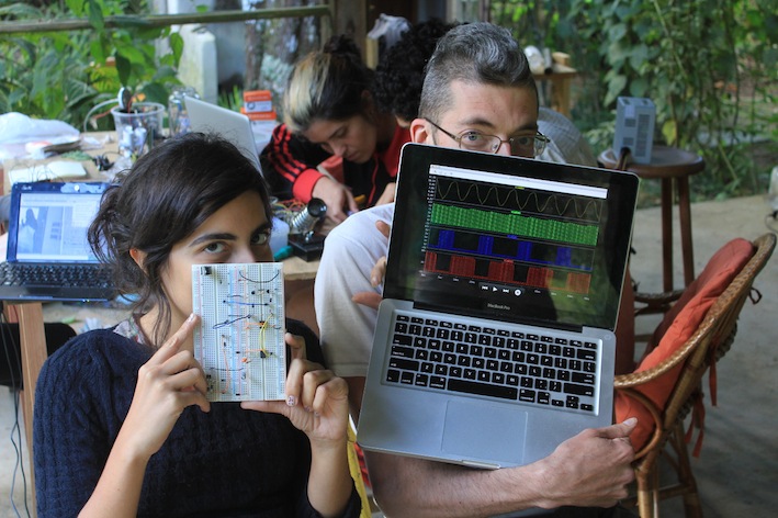
- Circuito sendo montado em protoboard:
http://cambiosara.tumblr.com/post/60986977857
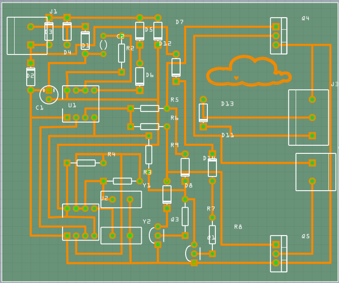
- Desenho final do circuito impresso do Grid-Tie Inverter:


(destaque para a figura da garotinha semeando, feita pelo Surian_dos_Santos e pela Tainá_buzzatti! ♥)
- Desenho feito utilizando Fritzing: